As I have mentioned several times already, the current project will incorporate several new solutions compared to the previous STAN ONE mission. The purpose of this chapter is not to discuss each individual subsystem in great detail, but rather to introduce the concepts behind their implementation. Of course, the theoretical background and technical details will be covered separately in dedicated articles on the blog. For now, let’s dive in.
Everyone knows that people are rarely fully satisfied with what they have achieved. Once one goal is reached, the next one appears on the horizon. My case is no different. My journey with stratospheric flights started with basic scientific experiments such as temperature and pressure measurements. Later, I added measurements of the forces acting on the payload during flight and experiments related to light intensity as a function of altitude. However, let’s be honest, after a certain point, these become relatively common and well-established solutions. Naturally, the desire arises to try something more ambitious. That is why, for the current project, I decided to focus on three new areas.
The first one is GPS positioning and payload tracking. Some may rightfully ask: if you’ve already launched several stratospheric payloads, GPS tracking seems like an obvious feature, why didn’t you use it last time? The answer is quite simple. I wasn’t flying alone. During my previous flights, I participated in missions involving multiple teams, which meant that payload tracking was already provided as part of the overall mission infrastructure.
The current tracking system is based on the NEO-6M GPS module, a popular and inexpensive solution commonly used in location-tracking projects. It provides latitude, longitude, altitude, and time information. This data can then be transmitted to a microcontroller through a UART interface using the RX and TX lines. Thanks to its compact size and relatively low power consumption (approximately 70 mA maximum at 3.3V), the module is also well suited for stratospheric applications.


In the STAN TWO project, the NEO-6M is connected via RX and TX lines to a LoRa Wireless Stick Lite V3 module based on the ESP32-S3 microcontroller, which represents the second major addition compared to previous flights. The GPS position is updated every second to ensure the data remains as current as possible. Position reports are transmitted using the SX1262 radio transceiver integrated into the module. To comply with regulations governing the license-free 869.525 MHz frequency band used by this project, telemetry packets approximately 16 bytes in length are transmitted every 20 seconds. Under these settings, the transmission airtime is roughly 1.5 – 1.7 seconds. Additionally, all position data, along with timestamps and altitude information, is stored locally on an SD card to maintain a complete flight log in case individual packets are lost during transmission.


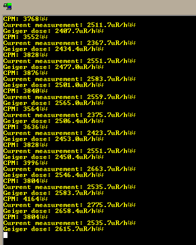
The third major technical addition is a Geiger-Müller counter designed entirely by myself. The detector is based on an STS-5 tube, although it may eventually be replaced by an SBM-20. Both are popular Geiger-Müller tubes used for detecting ionizing radiation, primarily beta and gamma radiation. They are relatively easy to obtain, their documentation is available in Russian (so finally my knowledge of Russian turned out to be useful), and they can be interfaced with microcontrollers when combined with an appropriate high-voltage supply circuit. Their typical operating voltage is around 400 V, which means the design must include a safe high-voltage power supply module and proper isolation.

I will describe the Geiger-Müller counter in much greater detail in a separate article dedicated specifically to individual hardware modules. For now, I can say that the pulses generated whenever a particle is detected are counted by the ATmega32 microcontroller using the INT0 external interrupt configured for a rising edge trigger. Naturally, the system had to be carefully calibrated, and at this stage I can confidently say that the results are very satisfying for an amateur instrument.

More updates and technical articles are coming soon. Stay tuned!